While restoring one of my vintage computers, I needed to replace the original PROM chips that were missing when I obtained it. The original chips were MMI 6301-1J parts, which are extremely difficult to find with the correct markings. In order to use vintage parts of a similar age, I located Texas Instruments SN74S287 PROM chips with reasonable 1976 date codes from a seller on eBay.
I expected that these would use the same programming methodology used for the National Semiconductor parts of the same number. Unfortunately, it appears that while Texas Instruments used the same base part number, they use a different programming technique.
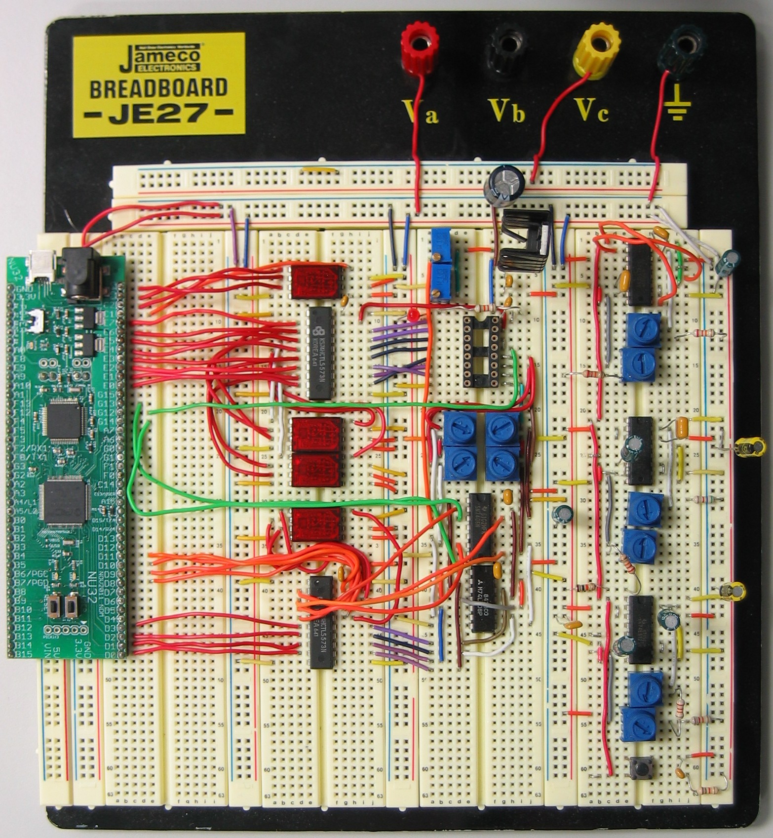
As none of the programmers that I had available to me allowed me to program the chips that I purchased, I was forced to build my own.
I searched extensively for as much information regarding these parts as I could find. Basically, the programming steps are the following:
- Select address to be programmed
- Select single bit to be programmed
- Apply 10.5v to Vcc
- Select chip(active low)
- Wait 10ms for fuse to blow
- Deselect the chip
- Reduce power back to 5v
- Repeat for each bit to be programmed
The timing involved with this is critical. If the pulse is too short, the fuse may not blow properly. If the pulse is held too long, the part could be damaged. Additionally, the intervals between steps must be matched to the data sheet, or the programming mode will not be activated and the chip or programmer could be damaged.
Some of the designs I found were merely a set of address and data switches with a push button to apply 10.5v to Vcc. While this may work sometimes, it would likely result in a number of bad chips, which was discovered by the users. I only had two of the chips, and I needed both of them. If I had a bad burn, I would have to purchase new chips and wait longer to complete my project.
During my research I found that these parts are similar to the MH74S287 by TESLA and use the same programming method. There are a number of articles regarding the programming of the TESLA parts, although most are not written in English. Fortunately, the schematics were easily recognizable!
As a side note, it appears that while the TI SN74S287 programs zero bits, the TESLA MH74S287 appears to program the bits to be one. If you attempt to replicate this with the MH74S287, please consult the data sheet!
My first attempt at a programmer involved the column of 74LS123 retriggerable monostable multivibrators as one-shots on the right in the image above. It worked to create the necessary pulses, but, even after adding additional components to eliminate bouncing of the push button, the circuit was not as reliable as I desired. Using it would have required manually setting the address and data bits, greatly increasing the amount of time to program the entire chip.
Consequently, I pulled a board built around a Microchip PIC32 processor from my junk box and connected it to the breadboard. It was overkill for this project, but had lots of I/O pins and was easy to interface with a laptop. I had never used it before, and this seemed like a good time to play with something new.
I used a pair of latches to buffer the address and data signals between the PROM and programmer logic. The programming voltage adjustment is handled by an adjustable voltage regulator. One of the pins on the PIC32 was connected through an open collector inverter to a resistor to adjust the voltage output which was in turn connected to the PROM chip’s power supply.
The programming bits were also supplied through open collector inverters, to ensure that the correct resistance is applied to the pins not being programmed while grounding the programmed pin.
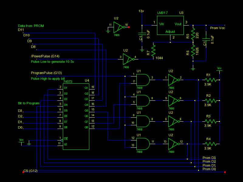
The schematic illustrates how the latch was used to buffer the data pins. An inverter was selected to adjust the voltage regulator as it ensures that the voltage is set to 5v when the PIC32 is powered on. This avoided applying 10.5v to the PROM being programmed while the circuit was initializing.
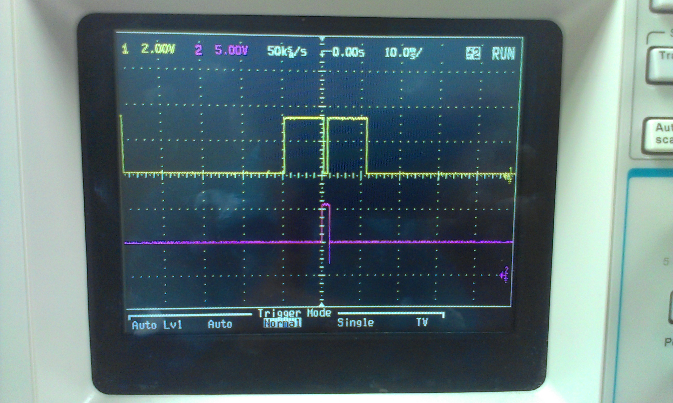
The resistance values were calculated and then verified by using ngspice to simulate the voltage adjustment circuit before installing it on the breadboard. By using potentiometers, the resistance was carefully adjusted to ensure that the voltages applied were correct by manually setting the programming select line high and then low.
The PIC32 was programmed with a simple program to appear as a serial device. It responded to an address set, data set, bit select, and program commands. After each command it responded with the current status of each port. The program command handles the timing for the chip select and program lines, ensuring that the timing follows the specifications on the data sheet.
A small script interfaced with the PIC32 through the virtual serial interface. The script started by reading in the data to be programmed. For each 4 bits of data, the script sets the address and data, and then steps through the bits that required programming, applying a program pulse for each one. Bits set to zero were programmed, and bits set to one were left in their default state.
As the circuit appeared as a serial port, I used a terminal program for testing. I sent the initial commands one at a time to view the resulting voltages and signals. By stepping through the commands, I was able to fine tune the various resistors required to obtain the correct programming voltages. This process also allowed me to program the first few data values by hand to observe the results slowly and ensure that the circuit was operating correctly.
In the video below, you can see the address selected (middle two values), current state of the bits in the PROM (on the left), and the desired final state (on the right.) If you watch carefully you can see as the original F state of the PROM is adjusted to the final state one bit at a time.
Hello !
Nice work, congratulations !!
I plan to program Tesla MH74S287, so I have two questions :
– First did you came to actually program some Tesla parts ??
– Second, my search on the web for Tesla datasheet gave no results.
Can you help me with this, please ?
Many thanks and regards
GC
Hi, I have not used the Tesla parts, just the Texas Instruments SN74S287.
Finding data sheets is not too hard. There are some at datasheetarchive.com and here: http://www.teslakatalog.cz/MH74S287.html The original data sheet appears to be here: http://www.tesla-ic.com/pdf/mh74s287.pdf
I also found programming examples in the Amatérské Radio magazine archives.
A programmer that claims to be able to program them is the: http://www.elnec.com/device/Tesla/MH74S287/
Hi,
I programmed succesfully two MH74S287 this morning with an Elnec Beeprog+.
Marc