As indicated in my previous posting, I had issues with the switches that I purchased and their usage in the OSI-300 mini. I took apart one of the switches in order to get a closer look at how it worked and if the switch could be adjusted to work properly for my application.
The switch has three blades that are made as extensions to the individual leads. The switch connection is made by a metal slider that has four contact points, two on each side of the blades. These contact points are supposed to be sized such that they do not contact the outer two blades at the same time. The options to fix this are to separate the blades with more space, or shorten the contact points to avoid shorting the outer blades.
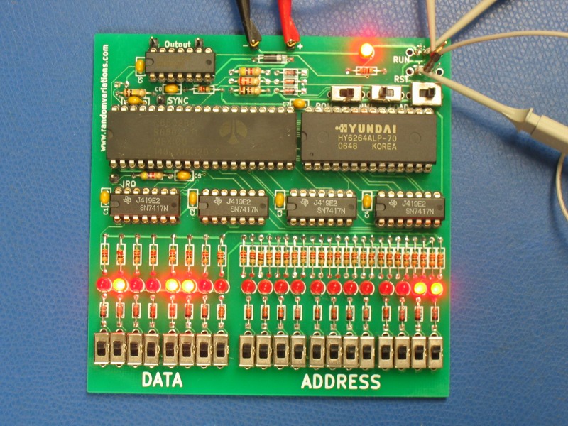
I looked at a similar component at work and found that they had shortened the slider slightly by bending the outside corners of the four contacts. I took a pliers and did the same to two of the switches that I had. After much trial and error, I was able to adjust the switch to prevent the shorting that I had seen. I soldered them in place to complete the prototype and took the image above.