TI Silent 700 Model 733 Keyboard Logic

TI Silent 700 Model 733 Keyboard

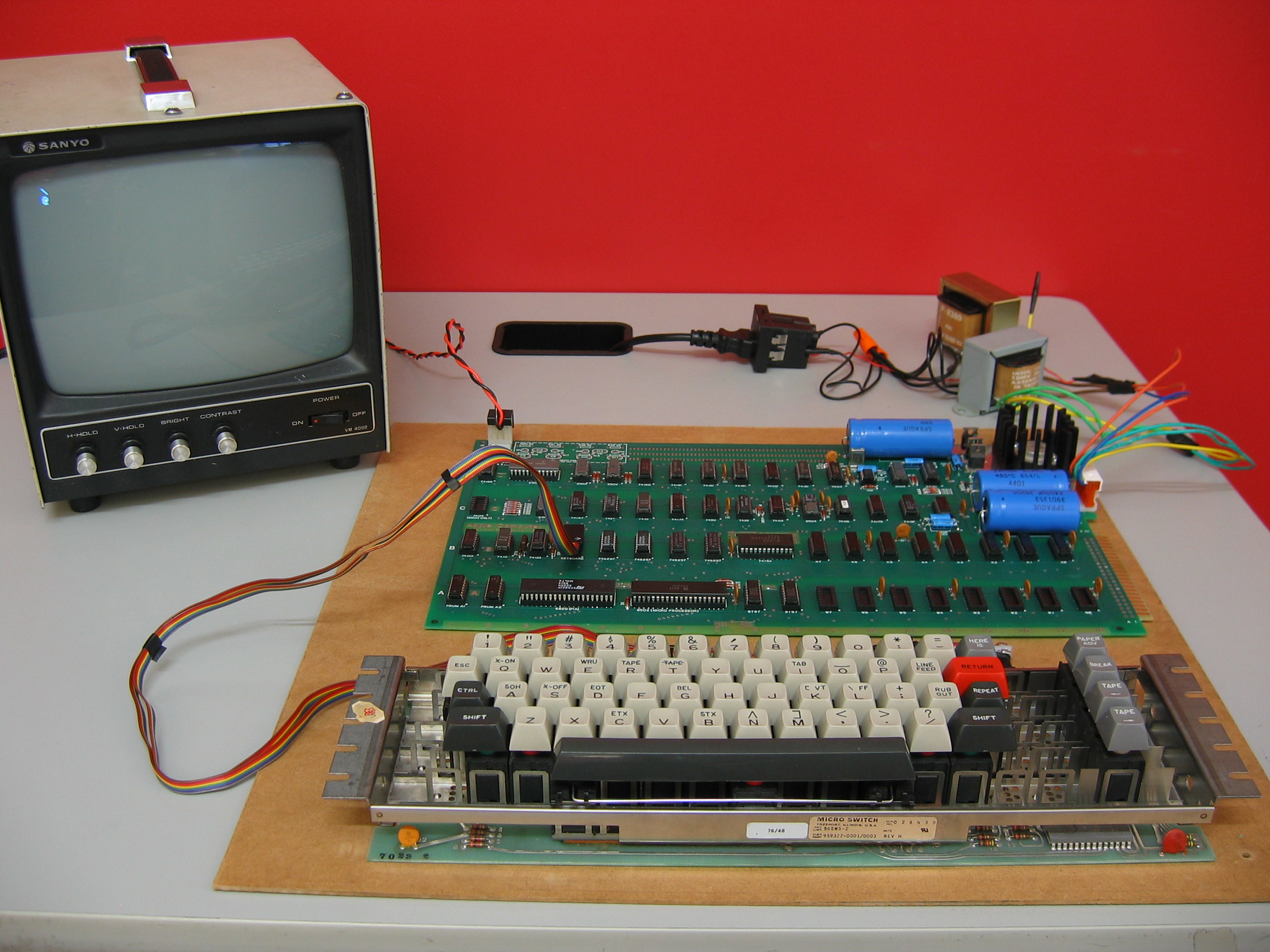
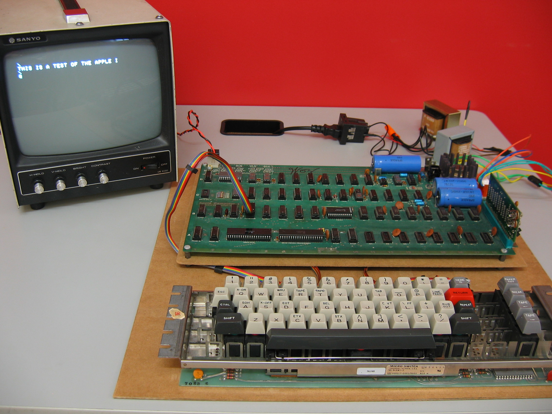
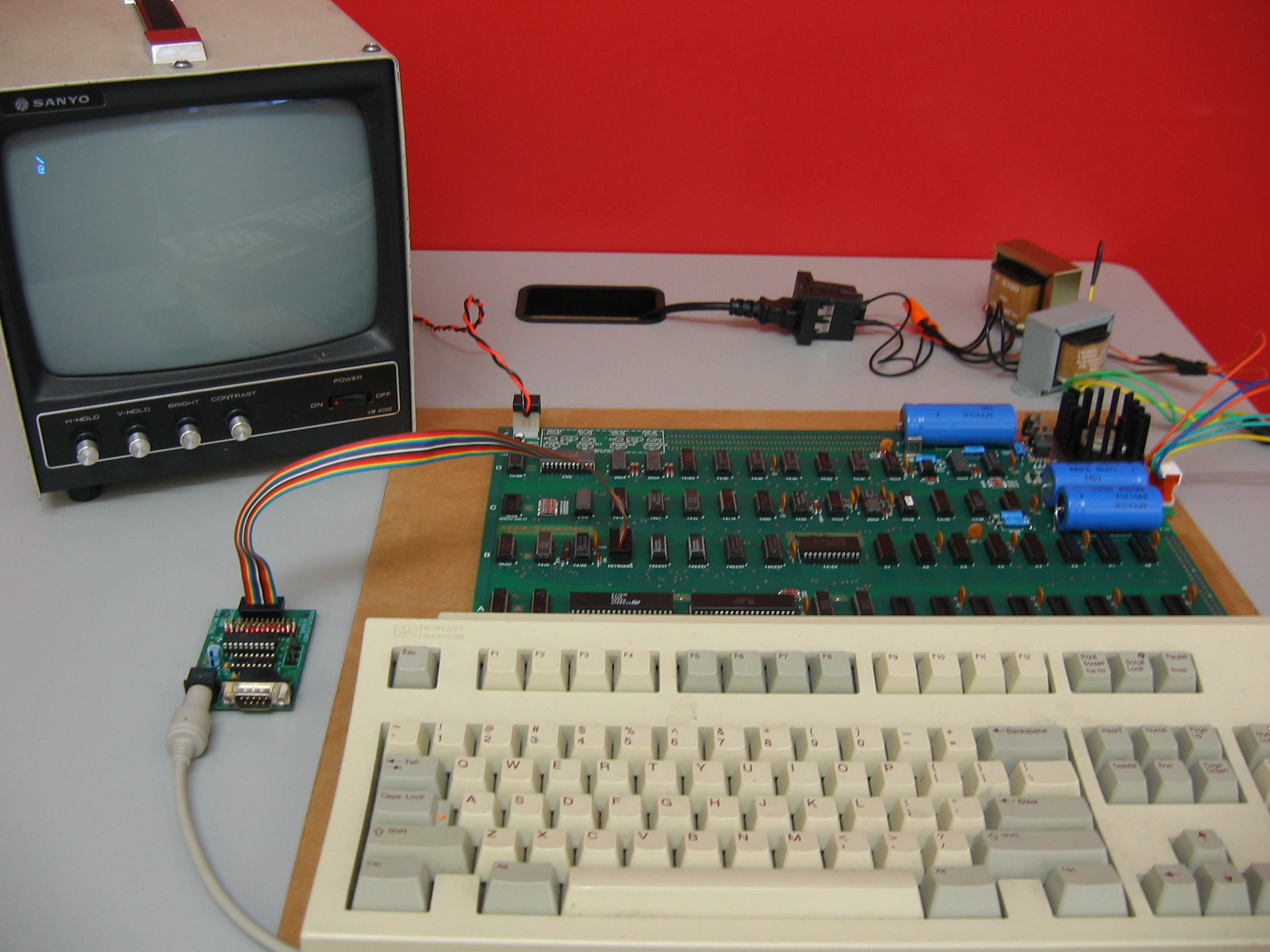
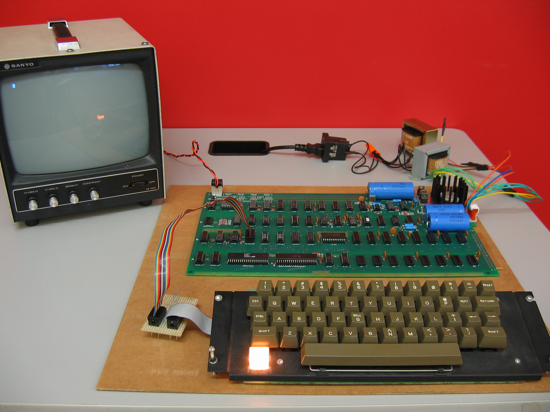
While working on attaching a TI Silent 700 Model 733 keyboard to an Apple 1 Computer, I transcribed a schematic for most of the logic.  This keyboard is fairly simple, generating only ASCII upper-case, symbols, and control characters.

The largest chip is labelled AMI SW20276K and is used to generate the ASCII output from the hall-effect switches on the keyboard.  This chip has the following connections:

 1-13: keyboard matrix
   14: N/C
15-21: data bit 1 through bit 7
   22: "shift"-able character pressed
   23: "control"-able character pressed
   24: key pressed
   25: N/C
   26: +5v
   27: ground
   28: -12v

Pin 13 on the encoder is connected to one of the outputs from the N, M, K, L, O, and P keys, which are the only keys that have characters that can be used with both the control and shift keys at the same time.

Interestingly, each of the hall-effect switches has two outputs.  For the ASCII generating keys, these are connected to form the matrix.  The switches are continuously powered from +5v, and the matrix does not appear to be organized using the more common scan/sense form.  With the exception of the two tape direction, shift and control keys, all keys are active low.  The shift and control keys output a high value when they are pressed.  The tape direction keys output a pulse low.  Each key has a colored stem.  Red stems output a low.  Green stems output a high.  White stems output a pulse low.

The key pressed pin (24) is active as long as a key is pressed.

The signals from the other output pins are all latched when a key is initially pressed.  These can be captured on the rising edge of the strobe.

TI Silent 700 Model 733 Keyboard Logic

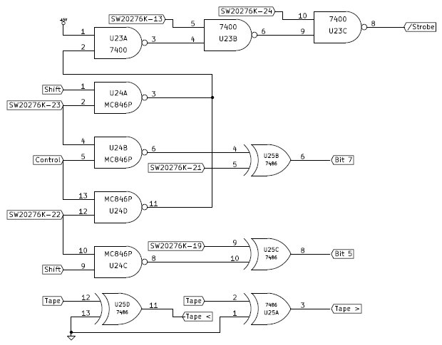
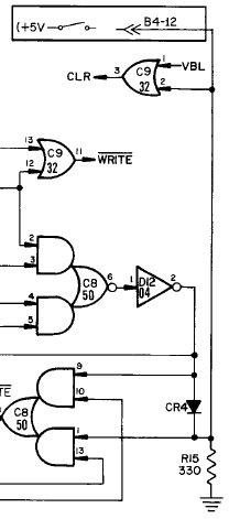
As can be seen in the schematic, the output from the encoder is presented to three chips which control the strobe output and bits 5 and 7 of the ASCII result .

The 7400 Quad NAND chip is configured to ensure that a key down strobe is only emitted when a valid sequence of keys is pressed.

The MC846P Quad NAND is used to detect the control and shift keys, using two XOR gates from the 7486 to invert the appropriate bits that form the correct ASCII character.  The MC846P has two outputs tied together in this design.  According to the datasheet, this is a valid configuration for this part, which is why it was used instead of an additional 7400.

The SW20276K has an interesting feature.  It outputs the ASCII codes with bits 5 and 7 inverted.  In the above circuit, the XOR gates are normally used to invert these bits to their normal ASCII values.

A look at the keyboard shows why this circuit works.  The keyboard does not use today’s modern shift values, but instead matches the shifted characters in such a way that a simple bit change can be used to alter their position within the ASCII table.  For example, a number 9 is 39 in hex, or 00111001 in binary.  Shifted, this becomes the ) character on the TI keyboard.  A ) in ASCII is 29 in hex, or 00101001 in binary.  Only one bit value needs to be changed to alter the character.

The two remaining XOR gates in this circuit square the pulses generated by the tape left and right keys.  The result is a 228usec low at the edge connector.  Note: This could be used for an active low reset, but is not long enough to clear the screen on an Apple 1 when inverted.

Lastly, the remaining gate on the 7400 (not shown) is unused.  Pin 13 is connected to +5v, and the remaining input and output are both left unconnected.  This would be useful if an inverter were needed for the strobe or one of the other buttons.

Converting the IC Station PS/2 Keyboard Interface to ASCII

IC Station PS/2 to Serial/Parallel/IIC/TWI

At VCFMW this fall,  this small board was passed to me to see what I could do with it.  The silkscreen on the back indicates that it is from IC Station.  It is designed to allow a user to connect a PS/2 keyboard to a computing device without having to poll the keyboard signals directly.  It provides an 8-bit parallel output, a 5v serial output, and either I2C/TWI output.

Our original thought was that the adapter would allow us to connect a PS/2 keyboard to a vintage computer that required a parallel input.  However, upon connecting a keyboard, and monitoring the signaling, I discovered that it was only mirroring the values provided by the keyboard to the parallel, serial, and IIC/TWI outputs.

I set it aside, until I had a chance to look at it further, which I did a short time later.

Examining the system closely, I realized that it uses an STM8S003F3 processor.  This is a small 8-bit MCU with 8Kbytes Flash, 1Kbytes of SRAM, and 128 bytes of EEPROM.  It has an internal clock, capable of running at 16Mhz, three timers, and 16 I/O pins.  It uses a single wire interface module (SWIM) for development and programming.

With that knowledge, I ordered an ST-Link programmer and waited for it to arrive.

Upon arrival, I soldered a wire to the reset pin  to the board and connected the programmer to read the contents of the embedded Flash.  Unfortunately, this processor has a read out protection bit, and it was set.  As a result, I was unable to read the existing program.  However, I could reset it, and clear the Flash, which I did.

I was then able to program it with my own program, which reads the values from the PS/2 keyboard and then uses a table to convert them to the correct ASCII values.  These values are presented on the parallel data lines, and the KEY pin is toggled as a strobe.

The Apple 1 requires a reset and clear screen option, which I mapped to F1 and F2.  I use the SCL to act as the clear screen output and the SDA pin to act as a reset.

The board will need a protection diode on the clear screen line, much like I discussed when  attaching a Texas Instruments Keyboard.  Mike Willegal uses this same technique for his PS/2 Keyboard adapter.

The Flash memory contains plenty of room for additional features and this could be used with a mouse, keypad, or the two PS/2 pins could be used as generic I/O pins.

Here is information regarding the connections between the pins available on the board and the STM8S:

PS/2
Clock:  Port D, Pin 4
Data:   Port A, Pin 1
Serial
TX:     Port D, Pin 5
RX:     Port D, Pin 6
Parallel
D0:     Port C, Pin 3
D1:     Port C, Pin 4
D2:     Port C, Pin 5
D3:     Port C, Pin 6
D4:     Port C, Pin 7
D5:     Port D, Pin 1
D6:     Port D, Pin 2
D7:     Port D, Pin 3
I2C/TWI
SDA:    Port B, Pin 5
SCL:    Port B, Pin 4
Enable: Port A, Pin 3
Other:
Key:    Port A, Pin 2

Using a TI Silent 700 Model 733 Keyboard with an Apple 1 Computer

TI Silent 700 Model 732/733 Keyboard with Mimeo

Over the summer I acquired a vintage keyboard that matched the one used on the Smithsonian’s Apple 1 Computer.

Some investigation revealed that this is the keyboard that Texas Instruments used in their TI Silent 700 series of terminals.  This keyboard (Micro Switch part 56SW5-2 or Texas Instruments part 959327-0001/0003) was one of the models used by the 733 ASR/KSR terminal.

An examination of the maintenance manual reveals that the keyboard is an upper case only ASCII keyboard, with the following signals available:

 1 Bit 6 (Data)
 2 Speed (Direct Connection to Switch Connector)
 3 Bit 1 (Data)
 4 Bit 3 (Data)
 5 Repeat (Special Function Output)
 6 Tape (Special Function Output)
 7 Tape (Special Function Output)
 8 Ground
 9 +5V Power
10 -12V Power
 A Bit 7 (Data)
 B Bit 5 (Data)
 C Bit 2 (Data)
 D
 E Break (Special Function Output)
 F Online (Direct Connection to Switch Connector)
 H Strobe Pulse
 J Here Is (Special Function Output)
 K Paper ADVance (Special Function Output)
 L Clock (For Debounce Circuit)

The REPEAT, BREAK, HERE IS, and PAPER ADVance switches are all connected through a 10k resistor to +5v, and connect to ground when pressed.   I connected the data, power and ground connections directly to the corresponding pins on the Apple 1 keyboard connector.  The reset input  was connected to the BREAK key, as the Apple 1 expects a connection to ground when pressed.

However, before using the Apple 1 or Mimeo, the screen needs to be cleared.  The Apple 1 is designed for a connection to +5v through a normally open switch, which is not provided by this keyboard.

Apple 1 Clear Screen Input

In this part of the Apple 1’s design, the inputs to the chips at C8 and C9 are normally held low by resistor R15.  Besides being driven by the clear screen button, the inputs are also driven by an inverter at D12, through diode CR4.  The diode protects the output of the inverter from to much current when the +5v is supplied during the time when the clear screen button is pressed and the inverter output is low.

There are many ways to convert the active low signal from the keyboard to the active high signal required.  One option is to insert an inverter between the keyboard and the input on the Apple 1.  This would require an additional diode to be placed to protect the normally low output from that inverter when the inverter at D12 drives it high.  This creates a wired-or style circuit.

The keyboard itself has one unused NAND gate with one input connected to +5v.  The second input and output appear to not be connected.  Normally, I would have cut the trace from one of the extra buttons and routed the signal through the NAND and back to the output trace.  However, I was hesitant to make permanent changes to the keyboard.  I may wish to use it elsewhere!

I could also have added an external chip to perform the inversion.  However, I felt that this would be a waste as most of the chip would be unused.  In either of these cases, I would still need to insert the diode to protect the gate.

Apple 1 Keyboard Clear Screen Inverter

I wanted to look for an alternative method to adapt the output from the keyboard to the input that the Apple 1 expects.  I knew from my circuits classes that a transistor can be used as an inverter.  With some careful trial and error on a breadboard, I was able to simulate the circuit on the keyboard, and correctly design an inverter that would properly drive the clear screen input on the Apple 1.

With this final piece of the puzzle solved, I soldered the parts to the connector to the keyboard along with the wiring for the Apple 1 interface.  At this point, I made the choice to map  the clear screen switch to the PAPER ADVance key.

I tested it one more time with a breadboard, to ensure that the circuit worked correctly, and then connected it to the Mimeo above.  The clear screen and reset options worked perfectly.

Lastly, I tried the keyboard out on an Apple 1 Computer, with the results below.

TI Silent 700 Model 733 Keyboard with Apple 1

Using a PS/2 Keyboard with an Apple 1 Computer

PS/2 Keyboard with Mimeo

In addition to being able to use an Apple II Keyboard with an Apple 1 Computer,  Mike Willegal has put together a small kit which can be assembled to provide a PS/2 interface for either the Apple II or the Apple 1 Computer.

Mike’s solution features an ATtiny2313 configured to perform the PS/2 to Apple II or Apple 1 translation.  It also provides the ability to connect a serial connection to send data from another computer, or capture data being typed on the keyboard.

Mike also offers an assembled version for individuals who wish to avoid assembling their own.


Using an Apple II Keyboard with an Apple 1 Computer

Apple II Keyboard with Mimeo

Many years ago, I worked on repairing an Apple 1 computer.  At the time, I needed a keyboard and came up with a simple wire wrapped circuit to translate the signals from the Apple II keyboard connector to that expected by the Apple 1 computer.

The Apple II uses the following connection:

       +---| |----+
   +5v | 1     16 | NC
Strobe | 2     15 | -12v
~Reset | 3     14 | NC
    NC | 4     13 | Data 1
Data 5 | 5     12 | Data 0
Data 4 | 6     11 | Data 3
Data 6 | 7     10 | Data 2
   Gnd | 8      9 | NC
       +----------+

The Apple 1 uses the following connection:

       +---| |----+
~Reset | 1     16 | +5v
Data 4 | 2     15 | Data 8 (connected to +5v)
Data 3 | 3     14 | Strobe
Data 2 | 4     13 | NC
Data 1 | 5     12 | Clear Screen (switch to +5v)
Data 5 | 6     11 | -12v
Data 6 | 7     10 | +12v
Data 7 | 8      9 | Gnd
       +----------+

Wiring the two devices together was easy, with one exception. The Apple II keyboard has no switch for clearing the screen. Rather than alter the keyboard, I left two wires exposed for the +5v and clear screen connections, which clear the screen when touched gently together.

Wendell Sander has instructions on how the Apple II keyboard can be wired to the Apple 1 computer’s keyboard input, as well as how it can be modified to use the repeat key as a clear screen key.

For those interested in a  board they can simply purchase and use, VintageMicros sells a small adapter board, which includes a clear screen button.