Category Archives: Apple II

Apple IIgs 72-pin SIMM memory adapter

4/8MB 72-pin SIMM adapter

I recently purchased a ROM 01 Apple IIgs with the intention of using it to further my disk image explorations.  While it came with an Apple 1MB expansion card, I quickly realized that it would be useful to have more memory installed.

In searching for information regarding the memory expansion capabilities, I came across the postings outlining the RAMGS expansion boards from http://gglabs.us/  In it, the developer notes how it is possible to use FPM DRAM in place of the standard DRAM chips.  I realized that these same chips are those used on standard PC SIMMs.

Analyzing the circuits used by GGlabs, and comparing the memory portion to that of a standard SIMM, I realized that some simplifications can be made.  In particular, the SIMM multiplexes four CAS and four RAS signals to select the byte being read, this means that one of the dual 2:4 decoders can be eliminated by feeding the correct inputs into a single 2:4 decoder.

Due to the way that the IIgs performs memory refresh, it is important to ensure that both 4MB banks be refreshed together.  This is done by using a quad 2:1 mux.  The mux applies the correct input to the 2:4 decoder to ensure that CAS0 and CAS2 (for the first 4MB bank) are selected and that they are routed also to CAS1 and CAS3 (for the second 4MB bank.)  The final 2:1 multiplexer is used to ensure that the write line is high during a refresh, as outlined in the GGlabs reference.

While testing a random assortment of 4MB and 8MB SIMMs that I have collected over the years, I found that this circuit works with EDO SIMMs as well as FPM SIMMs.

4/8MB 72pin SIMM to Apple IIgs memory expansion adapter

Visualization of Apple II Choplifter disk

Visualization of Choplifter for the Apple III was curious as to how the data on an Apple II floppy was related from track to track on a commercially generated disk.  As the Apple drives do not have an index sensor, sector zero does not need to be positioned relative to the index hole.

As my software records the time of each index pulse, it is relatively easy to line up the data from each track in graphical format.

To the right, you will see a visualization of each of the half-tracks of data from a commercially produced original copy of Choplifter.  The x-axis is the pulses from left to right, and the y-axis for each track is the time it took for the pulse to arrive.  Each track is stacked with track zero on top and track 79 on the bottom.

It is easy to see the data which falls into standard time intervals, and the “hash” that results from the random fluctuations as the heads pass over unrecorded spots on the disk.

Below is an image of track zero.  The beginning portion on the left is an unrecorded portion of the disk.  Then there is a sequence of 4×4 encoding, which is followed by the boot sector encoded in standard encoding as shown by the third line indicating 12 microsecond intervals.  A short burst of unrecorded data is followed by a large number of 4×4 encoded bytes.  Lastly, the remaining space on the track is unrecorded.

Interestingly, this disk is entirely encoded in 4×4 format, other than the boot sector.

Choplifter Track Zero

Information regarding the Choplifter boot process can be found at the below links:

http://www.hackzapple.com/phpBB2/viewtopic.php?p=4836

Computist Issue 23 pages 10-12:

http://computist.textfiles.com/ISSUE.23/

And for a visualization of how the heads read the above data:

http://pages.cpsc.ucalgary.ca/~aycock/ra/disk2.html

Controlling a Floppy Drive with a BeagleBone Black

BeagleBone Black Floppy InterfaceInspired by David Gesswein’s MFM Hard Disk Reader/Emulator I added a pair of voltage translator chips to a BeagleBone Black to control a floppy disk drive.

The software makes use of the BeagleBone Black’s programmable real-time unit subsystem (PRUSS) to control the head stepper and drive motor.  The PRUSS contains a capture unit running at 200Mhz, which is used to record the time of each pulse from the drive as the flux transitions pass under the head.  Using a 200Mhz clock results in a resolution of 5ns, which is easily able to capture the  4 microsecond cells used by the Apple Drive II controller.  The index signal is routed to one of the PRUSS controlled input pins for recording along with the timing data.

The software records 512000 samplings per track, with each sample consuming 4 bytes.  An additional 4k of space is allocated for the storage of the index pulse timings.  This results in 2052096 bytes per track, or 160320kbytes of data per disk.

The process of reading an entire 80 track disk takes about 8 minutes.

Reading floppy disks formatted for use on an Apple II results in a record of at least 10 rotations per track.  As many of the disks that I have in my possession are over 30 years old, multiple reads are useful in assisting with the recovery of data that may be barely readable.  I have found that using alternate floppy drives has occasionally produced tracks that are read correctly where another drive has had issues.

Once the timings are available, I can turn them into a stream of zero and one bits by performing an appropriate sampling function on the data.  The simple method for Apple II disks is to simply divide the time by 5microseconds.  The integer portion of the result is used as the number of zeros to shift before a single one is added.  This captures normal disks where the times are roughly 4, 8, and 12 microseconds.

As the processing is all handled in software, more complex algorithms can be designed.  Of particular use is one that follows the state machine as described in “Understanding the Apple II” by James Sather.

Once the general bit stream is formed it can be saved, similar to an EDD format.  If  the synchronization bits are stripped, then it can be saved as a nibble (.nib) file.  Lastly, if the bit stream is further processed, emulating the DISK II and DOS RWTS routines, a final disk image can be generated.  This last step is useful in validating the original disk image of normal DOS disks without copy protection as each sector has a checksum.  With multiple copies of each track available, it is possible to select a good copy of each sector and save it individually, creating one good image out of multiple passes.


Creating Apple disk images with the Central Point Deluxe Option Board

The Central Point Deluxe Option Board can be used to read floppy disks written on an Apple II in a standard 5.25″ drive on PC running DOS.

The TransCopy (TC.EXE) software automatically detects some Apple disks and copies them to an image with one track.  The result is a bit-level image of the disk much as an Apple disk controller card would see it.

One issue with these images is that the image contains only one copy each track.  This can be used to make standard disk images, but often more data is required if a sector crosses the index pulse.

Fortunately, the TC.EXE executable can be patched relatively easily.  Changing 8 select bytes will cause TC.EXE to believe that every disk is an Apple disk, and copy 16Kbytes or even 32Kbytes of data to the image file.

Before the TC.EXE executable can be patched, it must be unpacked.   This is done with an unpack tool, such as can be found at: http://ftp.sunet.se/pub/simtelnet/msdos/execomp/unp411.zip

Running unpack on the 5.40 version of TC.EXE results in:

unp i tc.exe

processing file : TC.EXE
DOS file size : 41207
file-structure : executable (EXE)
EXE part sizes : header 512 bytes, image 40695 bytes, overlay 0 bytes
processed with : EXEPACK V4.05 or V4.06

processing file : TC.EXE
DOS file size : 41207
file-structure : executable (EXE)
EXE part sizes : header 512 bytes, image 40695 bytes, overlay 0 bytes
processed with : EXEPACK V4.05 or V4.06
action : decompressing… done
new file size : 61600

The unpacked version of TC.EXE can be patched in two ways, one with the standard DOS debugger, or with a hex editor.

To patch the software with debug, the following can be done:

debug tc.exe
a 48c4
jmp 48d1

a 473a
mov dx,4000
nop

e cs:6838
3f

g

The first assemble command forces the program to detect all disks as Apple II disks.  The second assemble causes it to save 0x4000 bytes to the image file.  While the 4000 can be made larger, keep in mind that the DMA process will only load 64k at a time.  The final alteration changes the DMA count table to capture 0x4000 bytes (times two).  This should also be adjusted for even larger images.

The resulting program is run and will output images that are 0x4000 bytes in length.

To adjust the software in a hex editor, simply alter the following bytes and save:


4914: EB 0B
478A: BA 00 40 90
6888: 3F

or, to capture 32Kbytes at a time:

4914: EB 0B
478A: BA 00 80 90
6888: 3F

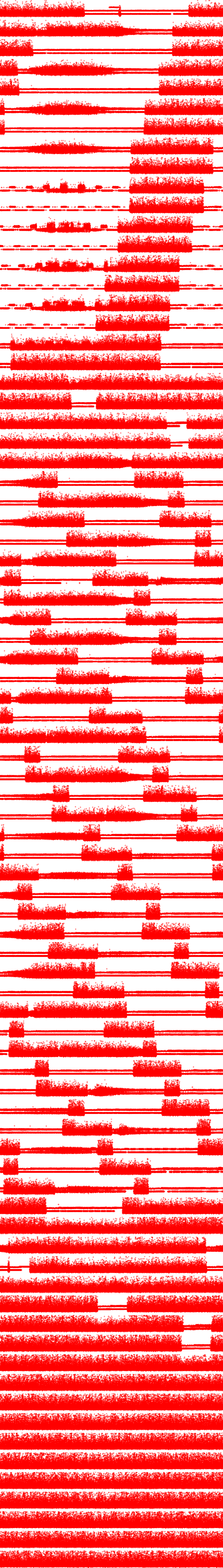
On my system, I have noticed that there is usually a burst of invalid data immediately after the track ends. However, data following it is valid until the end of the capture.

Information regarding the TC.EXE image format can be found here: ftp://ftp.blarg.net/users/genet/image_format.txt

Each track can be found by using the four bytes at 0x305+track*4 and shifting the results 4 bits left to obtain the index for the track within the file.

Generally, the first track is found at 0x4000, and for 32k captures, will be at 0x4000, 0x010000, 0x020000, 0x030000, and so on.

These tracks are captured starting immediately after an index pulse is detected and are thus index aligned.

I have had some success with extracting the last 16Kbytes of each track from an 80 track 32Kbyte TC.EXE image and duplicating them twice to create a standard quarter-track EDD disk image and using the image in an emulator.