Z80 Membership Card

Z80 Membership Card (Front)

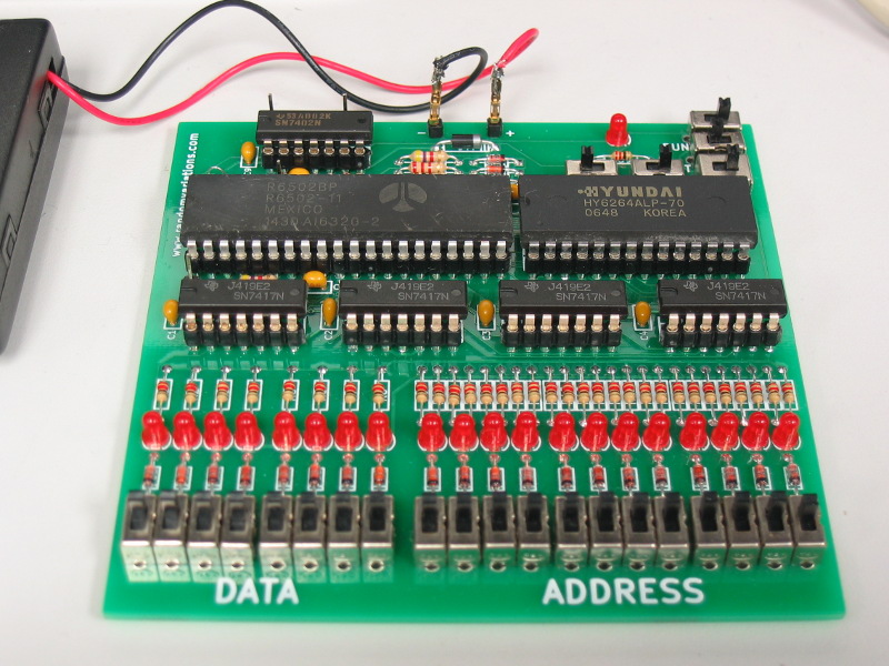
While at VCFMW last year, I spent some time talking with Lee Hart about his ELF Membership Card.  He showed me a new project that he had been working on with some others called the Z80 Membership Card.

Z80 Membership Card (Back)

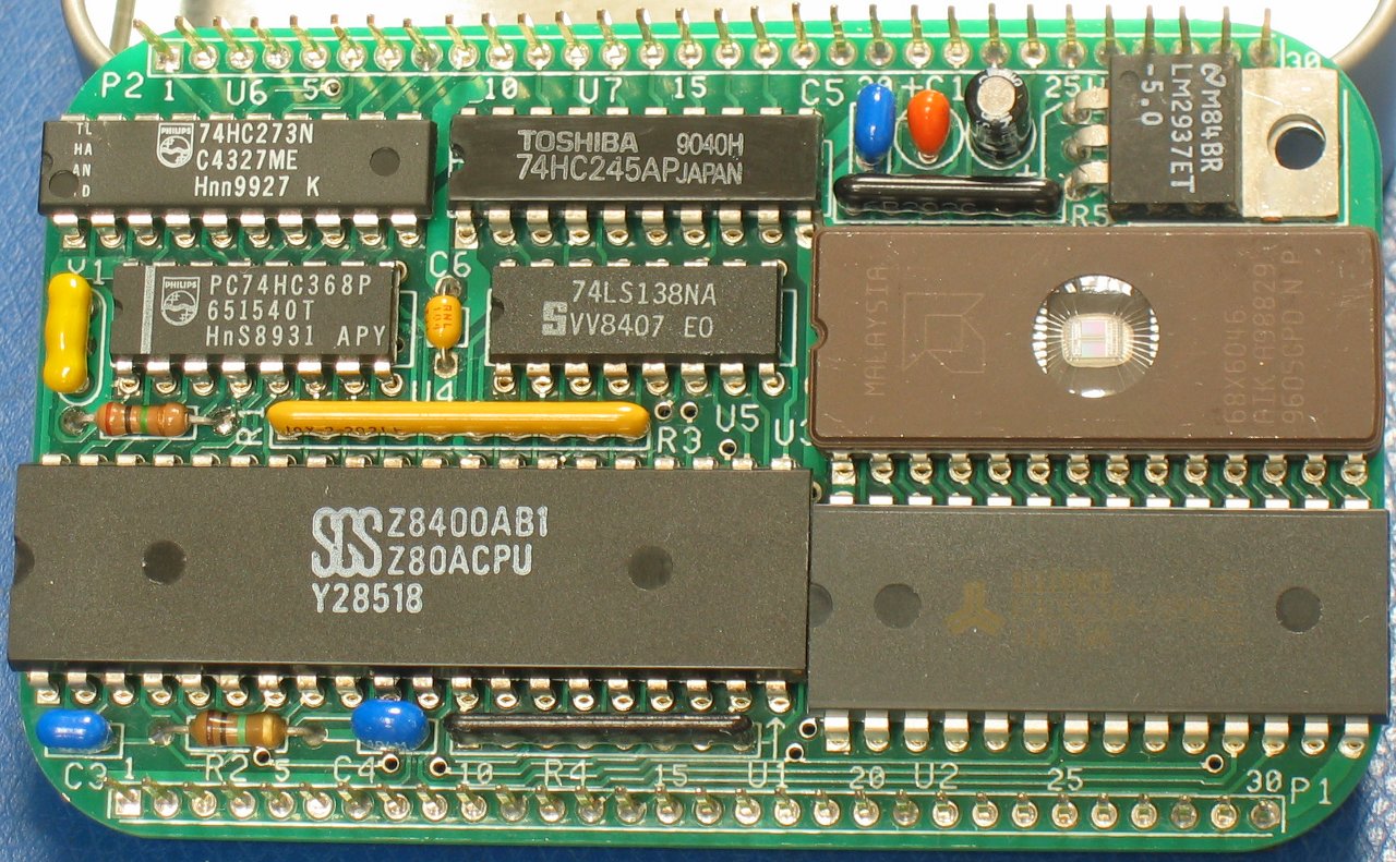
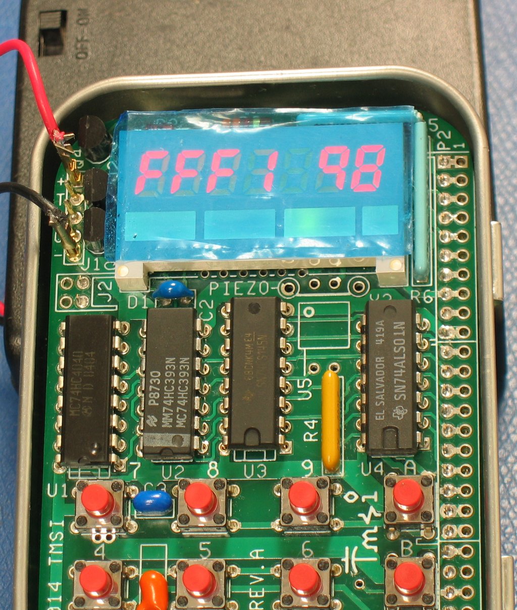
The base Z80 Membership Card contains a Z80 processor, 32k SRAM, and  32k EPROM, along with the necessary components to get them all working together.

Z80 Membership Card Front Panel

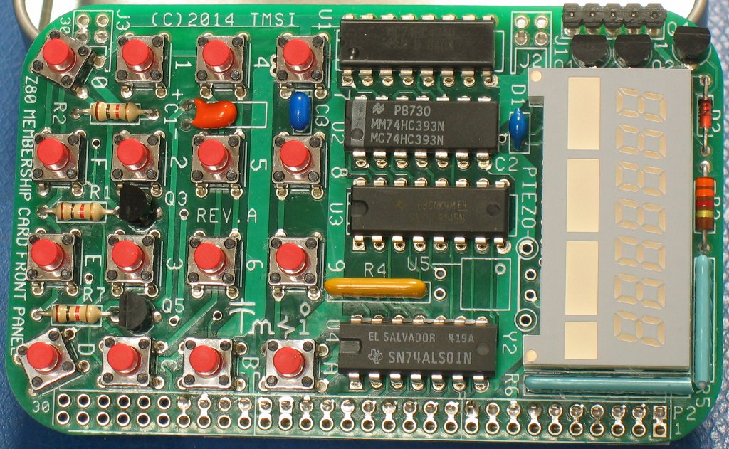
The front panel contains everything needed to interact with the membership card, 16 push button switches and a 7 digit display.  The scanning for the keyboard and display are all done through the same 8-bit input and 8-bit output ports.  Lee has also added components to provide for a serial port as well.

Z80 Membership Card Right Side

In addition to the impressive hardware, the Z80 Membership Card comes with some amazing software which interacts with Lee’s hardware design.  The software provides a full interrupt driven monitor which operates the front panel.

Z80 Membership Card Left Side

In addition to scanning the keypad and operating the display, it implements a 9600 baud serial port in software!  The monitor provides for the ability to view/change memory, view/change registers, single step programs, and upload code to memory using the X-modem protocol.

Running Z80 Membership Card In Altoids Tin

Oh, and it lets you do this even while running your own code at the same time!

Lee’s Z80 Membership Card page can be found at:

http://www.sunrise-ev.com/z80.htm

Assembly of the membership card was straight forward, Although I did use a few techniques to get it to fit into the Altoids tin with the lid closed.

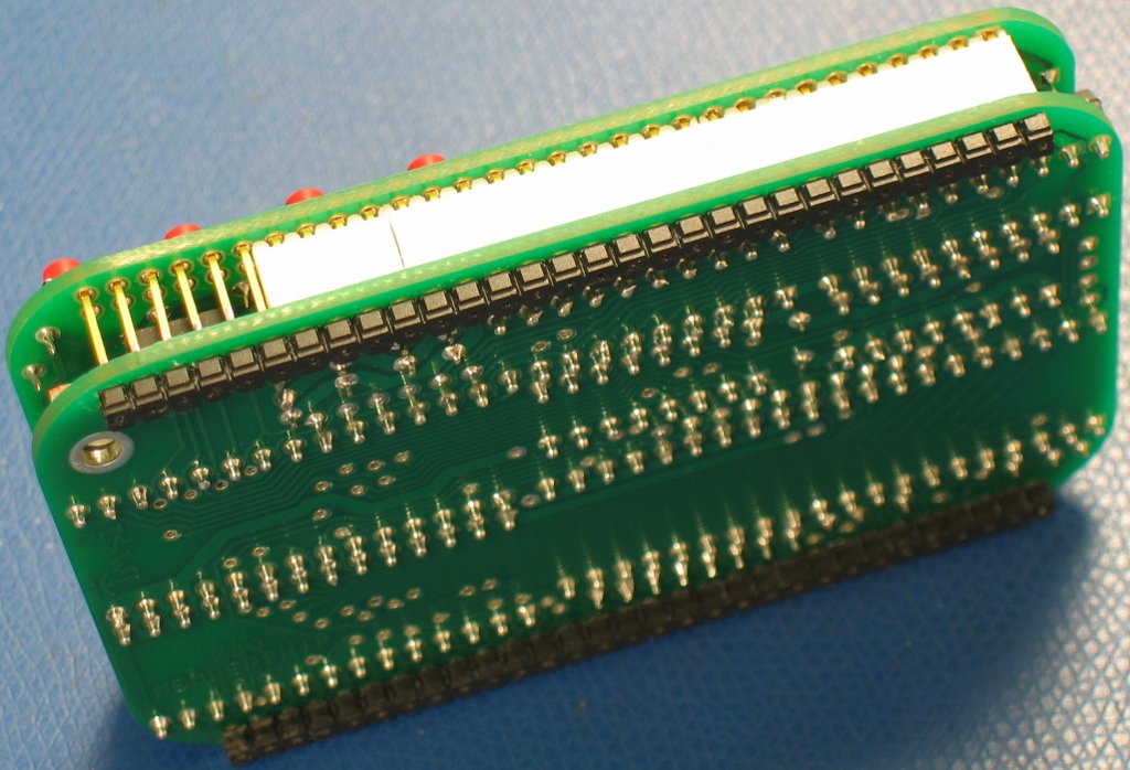
To start with, I purchased and used socket pins for all the chips.  The socket pins are almost (but not quite) like having the chips soldered directly to the board.  They allow for enough space between the boards that it isn’t necessary to trim the leads on the front panel as close as it would be required without them.

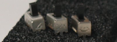
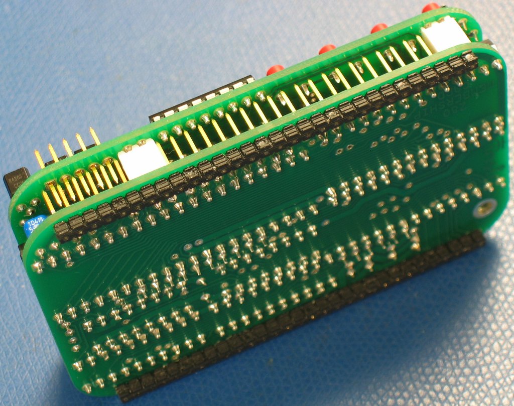
I then needed to trim the header on the left side.  While the right side has space for holes for the header to extend up into, the left side is too tight.  I trimmed off enough that the pins did not make contact with the front panel.  In hindsight, I could have left the four pins that pass through the corresponding two plugs long.  The body on both headers needed to be shifted to form the two feet along the sides on the bottom.  Carefully sinking the pins into the body prevents shorting to the surface upon which it sits.

The header for power and the serial lines also needs to be installed properly.  I pushed the leads through the plastic body to ensure the correct distance on top (approximately 7mm) and then soldered them in place.

While it took more than a few hours to assemble, I went slowly and carefully to ensure that it would fit properly in the tin.

Mini OSI-300 Parts List

IMG_9007_800x600

The final tally of parts is:

  • 1x R6502 NMOS 6502 CPU
  • 1x 6264 8k x 8 SRAM
  • 4x 7417 Hex Open Collector Buffer
  • 1x 7402 Quad NOR Gate
  • 21x 3mm red LED
  • 23x 1N914/1N4148 diode
  • 1x 1N4001 diode
  • 1x 100 ohm 1/4W resistor
  • 34x 220 ohm 1/4W resistor (I used 1/8W)
  • 1x 2.2k ohm 1/4W resistor
  • 2x 4.7k ohm 1/4W resistor
  • 1x 100k ohm 1/4W resistor
  • 8x .1in (2.54mm lead spacing) .1uF capacitor
  • 1x .2in (5.08mm lead spacing) 10pf capacitor (G0P/NP0)
  • 1x 40pin socket (if desired, turned pin preferred)
  • 1x 28pin socket (if desired, turned pin preferred)
  • 5x 14pin socket (if desired, turned pin preferred)
  • 6x breakaway header, single male pin
  • 24x 4.3mm x 8.6mm SPDT switch (C&K OS102011MS2QN1 or Jameco SS12D02)
  • 1x 6.8mm x 8.6mm DPDT switch (C&K OS202011MS2QN1 or SS22D07)

The mini trainer requires a 5v 1Amp supply to operate, although it does run fine from four AA batteries.

A Tale of Switches

Switches with logos
Switches with logos
Switch backs
Switch backs

While working on my mini OSI-300 Trainer, I encountered issues with the switches that I had purchased.  The seller advertised them as SS12D07 switches, which according to the data sheets that I had found, were non-shorting, single pole, double throw switches.

They were single throw, double pole, and fit the size and shape specifications.  Unfortunately, the ones I received were definitely not non-shorting, otherwise known as break before make, switches.  I found a single SS12D02 from Jameco in among my assortment of switches.  It appears to be non-shorting, and taking it apart I found that it uses a slightly different mechanism than the SS12D07 I had purchased.

I placed an order for C&K OS102011MS2QN1 switches, which are designed to be non-shorting (there is a specific shorting version.)   The C&K parts arrived and I have tested and confirmed that they are definitely non-shorting as expected.

In the images above, I show the parts from left to right:

  • Jameco SS12D02
  • C&K OS102011MS2QN1
  • T.O.Y SS12D07 (shorting)

Both the Jameco and C&K parts have two small vertical slots on the side.  The T.O.Y part has an indentation on the opposite side, which can be seen in the second image.

For my mini OSI-300, the T.O.Y parts are usable for all but the Run and Reset switches.  The Data and Address switches are configured as single pole, single throw.  The NMI switch has a resistor to prevent a direct short to ground, and the ROM switch does not switch between power and ground directly.  The Load switch is configured as a double pole, single throw switch as well.

In general, I have had the expected results when purchasing parts from places other than the big parts houses such as Mouser, Digi-key, Jameco, etc.  I find that looking closely at images and reviews improves the odds of receiving a working part.  Out of the ten 6264 SRAM chips I received, although all were marked with the same markings on top, they all had different tool marks on the body, markings on the backside, and three were completely non-functional.