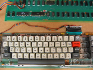
While working on attaching a TI Silent 700 Model 733 keyboard to an Apple 1 Computer, I transcribed a schematic for most of the logic. This keyboard is fairly simple, generating only ASCII upper-case, symbols, and control characters.
The largest chip is labelled AMI SW20276K and is used to generate the ASCII output from the hall-effect switches on the keyboard. This chip has the following connections:
 1-13: keyboard matrix
   14: N/C
15-21: data bit 1 through bit 7
   22: "shift"-able character pressed
   23: "control"-able character pressed
   24: key pressed
   25: N/C
   26: +5v
   27: ground
   28: -12v
Pin 13 on the encoder is connected to one of the outputs from the N, M, K, L, O, and P keys, which are the only keys that have characters that can be used with both the control and shift keys at the same time.
Interestingly, each of the hall-effect switches has two outputs. For the ASCII generating keys, these are connected to form the matrix. The switches are continuously powered from +5v, and the matrix does not appear to be organized using the more common scan/sense form. With the exception of the two tape direction, shift and control keys, all keys are active low. The shift and control keys output a high value when they are pressed. The tape direction keys output a pulse low. Each key has a colored stem. Red stems output a low. Green stems output a high. White stems output a pulse low.
The key pressed pin (24) is active as long as a key is pressed.
The signals from the other output pins are all latched when a key is initially pressed. These can be captured on the rising edge of the strobe.

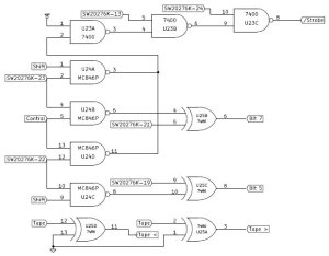
As can be seen in the schematic, the output from the encoder is presented to three chips which control the strobe output and bits 5 and 7 of the ASCII result .
The 7400 Quad NAND chip is configured to ensure that a key down strobe is only emitted when a valid sequence of keys is pressed.
The MC846P Quad NAND is used to detect the control and shift keys, using two XOR gates from the 7486 to invert the appropriate bits that form the correct ASCII character. The MC846P has two outputs tied together in this design. According to the datasheet, this is a valid configuration for this part, which is why it was used instead of an additional 7400.
The SW20276K has an interesting feature. It outputs the ASCII codes with bits 5 and 7 inverted. In the above circuit, the XOR gates are normally used to invert these bits to their normal ASCII values.
A look at the keyboard shows why this circuit works. The keyboard does not use today’s modern shift values, but instead matches the shifted characters in such a way that a simple bit change can be used to alter their position within the ASCII table. For example, a number 9 is 39 in hex, or 00111001 in binary. Shifted, this becomes the ) character on the TI keyboard. A ) in ASCII is 29 in hex, or 00101001 in binary. Only one bit value needs to be changed to alter the character.
The two remaining XOR gates in this circuit square the pulses generated by the tape left and right keys. The result is a 228usec low at the edge connector. Note: This could be used for an active low reset, but is not long enough to clear the screen on an Apple 1 when inverted.
Lastly, the remaining gate on the 7400 (not shown) is unused. Pin 13 is connected to +5v, and the remaining input and output are both left unconnected. This would be useful if an inverter were needed for the strobe or one of the other buttons.