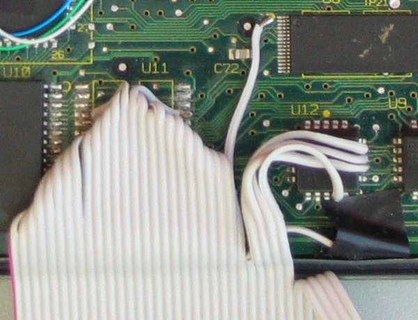
This image shows the final results from carefully tracing the pins from the flash chip back to the other chips in the credit card terminal. Through this connection, I was able to view the address and data lines as they were connected to the flash chip, along with the important select lines. I also added connections to the write line and chip enable lines for the main memory. Exposing these connections would give me a method of capturing the data not only from flash, but memory as well. The extra signals would make it possible to differentiate between the accesses to the two chips.
With this in place, I was ready to start. I configured the logic analyzer to store the data and address lines when the flash or memory was accessed, along with the read/write status line. I set the logic analyzer to run mode, and inserted the plug to power up the credit card terminal.
The results were immediate. There on the screen was the code currently running, starting at address 0. The following bytes were the program as it proceeded to initialize the hardware.
I had a long task ahead of myself, but, at least now, I could see inside the system to visualize how the terminal operated.